
Universal Asynchronous Receiver/Transmitter
UART No clock wire; both ends agree on speed
Use UART when two devices need a simple byte stream without a clock wire, such as a console or module command link. Start and stop bits give each receiver a timing reference. Both ends must agree on framing and baud rate, and software must define complete messages.
UART wiring, timing and transaction
Wiring
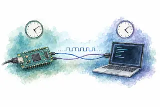
Device A TX connects to Device B RX. Device B TX connects to Device A RX. The devices share ground but each uses its own clock; there is no clock wire.
Connect each TX output to the other device’s RX input. With no shared clock wire, both ends must agree on the baud rate and frame format; each receiver uses its own clock to sample incoming bits.
Match the baud rate and connect compatible logic-level pins; RS-232 and RS-485 require transceivers.
UART frame
8N1: one start bit, eight data bits, one stop bit. Data travels b0 first.
Start = 0. The falling start edge establishes the receiver’s sampling schedule.
Timing and model details
Logic-level UART; 8 data bits, no parity, 1 stop bit. Bit time = 1 / baud; frame time = 10 / baud. Amber markers are ideal sample centers, not a specific receiver oversampling implementation. A high stop bit does not prove the payload is correct. Payload ceiling assumes back-to-back frames with no flow-control pauses. Narrow screens split the same continuous frame into consecutive windows.
Ten bit times carry one byte
A UART frame spends time on framing as well as payload. This worked example uses 8N1 at 115,200 baud.
115,200 ÷ 10 = 11,520 B/sMaximum one-direction payload with continuous framesOne frame takes about 86.8 µs. Idle gaps and application headers reduce useful throughput; baud is not bytes per second.
A USB console may contain a bridge
The active bridge buffers and translates between USB packets and UART bytes. A USB connector and logic-level TX/RX are different electrical and protocol interfaces.
UART is useful for logs and module commands. Software must add any message boundaries, checksums, or acknowledgments it needs.
Compare USB transactions →Follow a transaction
Advance here or in the transfer above. The highlighted operation and wire state stay on the same step.
value = 0; wait_for_start_low()
for b in 0..7:
value[b] = sample_center()
if sample_stop() != HIGH:
return FRAMING_ERROR
return received_byte(value)- Who drives
- Transmitter drives TX; receiver only samples its RX input
- Sent so far
- LOW start bit
- Response so far
- Start detected; data register not complete
Receiving data
Why this step mattersStep 1 of 10, Detect START. The falling start edge gives the receiver a reference for its own sampling clock.
Implementation notes
This is a conceptual hardware receiver, not a software timing loop. Firmware configures baud rate and 8N1, then reads received data with its framing and overrun status. The bad-stop fixture forces the final sample LOW; it does not simulate a particular baud mismatch. Define a policy to discard, flag, and resynchronize after errors. UART framing provides no acknowledgment or end-to-end checksum.
Common mistakes
Connecting TX to TX
Each transmitter connects to the other device’s receiver.
Confusing logic levels with RS-232
Use a suitable transceiver; the electrical signals differ. RS-485 also needs its own transceiver.
Trusting the stop bit as a checksum
A correctly framed 8N1 byte can still contain wrong data.
Measure a bit interval, decode the known byte, and inspect the stop sample. Exercise back-to-back traffic and receive-buffer overrun; include clock tolerance and interrupt-service latency in the design.
Further details and primary sources
- A falling edge starts the frame
- For this non-inverted UART, idle is high and the start bit is low. The receiver detects the start, then uses its local clock to sample near each bit center. Clock error accumulates across the frame.
- 8N1 describes the framing
- Eight data bits travel least-significant first, followed by no parity bit and one high stop bit. The ends must agree on baud rate, data length, parity, and stop configuration. Other UART frame formats exist.
- Separate bytes from messages
- A framing error means the expected stop level was missing; overrun means receive storage could not keep up. An application still needs message boundaries, validation, and flow control if its sender can outrun the receiver.
Example scope
Logic-level, non-inverted 8N1 UART. The selectable rates are teaching inputs, not guaranteed operating points. Voltage compatibility, oversampling, error tolerance, and optional RTS/CTS hardware flow control are target-specific.
Primary sources
Updated