
Inter-Integrated Circuit
I²C Many devices, two shared signals
Use I²C when several peripherals need to share a few controller pins. An address selects a sensor or memory on the same clock and data pair. This saves select pins, but address compatibility and the electrical load still need checking.
I²C wiring, timing and transaction
Wiring
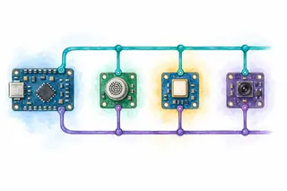
The controller, sensor at address 0x48 and memory at address 0x50 each connect to SCL, SDA and common ground. SCL and SDA each have a separate pull-up resistor to VDD. Every device can pull a line low or release it.
All three devices share SCL for timing and SDA for addresses and data. An open-drain output can pull a line LOW or release it; the pull-up then restores HIGH so another device can safely take its turn.
Dots mark connections; curved crossings keep SCL, SDA and ground electrically separate.
I²C transfer
Choose an address. Step through the write and its acknowledgments.
START: SDA falls while SCL stays high.
Timing and model details
One controller; ready targets at 0x48 and 0x50; 0x2A accepted as a single data byte. 18 clock pulses in this attempt. START and STOP are line conditions. Address and data windows each show eight bits followed by acknowledgment. For data bits, SDA changes only while SCL is low. Timing is idealized; rise time, setup/hold, arbitration and stretching are not simulated.
An address becomes a byte
The first byte combines a 7-bit address with one direction bit. The acknowledgment comes on a separate clock.
(0x48 << 1) | 0 = 0x907 address bits + 1 direction bitCheck the driver API: some take 0x48 and shift it for you; others expect an address byte. Shifting twice selects the wrong address.
Shared addresses or separate selects?
For two conventional peripherals, compare the signals needed at the controller:
I²C saves pins by putting a distinct target address on shared wires. SPI uses a select for each target and can move data in both directions together.
Excludes power and ground. Device support, bus loading, and required throughput still decide the choice.
Compare SPI timing →Follow a transaction
Advance here or in the transfer above. The highlighted operation and wire state stay on the same step.
start()
send(0x90) // address + W
if not read_ack():
stop(); return NO_TARGET
send(0x2A)
if not read_ack():
stop(); return DATA_NACK
stop()
return OK- Who drives
- Controller: SCL and SDA (open drain)
- Sent so far
- START only
- Response so far
- No acknowledgment sampled yet
Write in progress
Why this step mattersStep 1 of 6, START. START makes every target listen for the next address.
Implementation notes
These calls describe controller operations, not a specific driver API. Firmware normally configures a peripheral and checks its status. The teaching targets accept one byte directly; real devices may need command or register bytes. Bound waits for bus availability and completion. DATA_NACK is shown as a defensive branch; the two responding fixtures always accept 0x2A.
Common mistakes
Shifting the address twice
Check whether the driver expects the 7-bit address or a prepared address byte.
Guessing the pull-up value
Check rise time, bus capacitance, and the pin’s low-level current limit.
Treating every NACK as a wiring fault
Check the address, target readiness, and whether a read is intentionally ending.
Capture START, address, receiver ACK, payload, and STOP. Then test a missing target and a bounded wait for stretched SCL. Check analog rise time as well as the decoded bytes.
Further details and primary sources
- Release means high
- Open-drain outputs pull low or release; pull-ups create high. During a data bit, SDA stays stable while SCL is high. With SCL high, SDA falling marks START and SDA rising marks STOP.
- The receiver owns ACK
- Eight bits travel most-significant first. On clock nine the transmitter releases SDA; the receiver pulls it low for ACK. A high level is NACK. For a read, the controller receives data and NACKs its final byte before STOP.
- Keep ownership through a repeated START
- A repeated START begins another address phase without freeing the bus, often after selecting a register to read. Clock stretching extends a low clock period. Multiple controllers require arbitration; this lab uses only one.
Example scope
Conventional open-drain, 7-bit I²C teaching model. Addresses and payload are fixtures, not real device commands. Register formats and recovery procedures belong to each device manual; high-speed and Ultra Fast-mode variations are outside this lab.
Primary sources
Updated