Controls the decorative signal-flow background. The preference is saved on this device.
Explore ASIC.FYI ⌄
Embedded firmware · interrupts
Trace the event. Design the handler. Prove the timing.
A hardware-first guide to Cortex-M interrupts, priority, ISR design, shared state, measurement, and interview reasoning, built around one realistic control board.
Trace
Prioritize
Design
Synchronize
Debug
Hover or keyboard-focus dotted terms for a quick explanation.
ControlNode Lab | event-to-response explorerselect any block
This is an event-to-response map. It separates event producers, interrupt sources, the processor, outputs, and measurement points. Select a block to study its role.
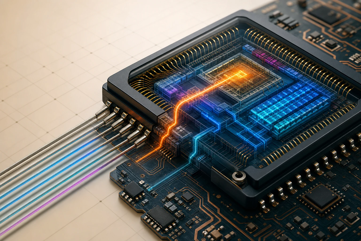
The comparator disables PWM through an independent hardware path. A configurable priority 0 reporting interrupt runs afterward to capture cause, service time, and recovery state. If physical trip time matters, read a hardware-captured event timestamp.
Comparator trip
Hardware PWM kill
Latched trip cause
Configurable P0 IRQ
Capture evidence
Recovery logic
Why this mechanism
Use direct hardware action when the safe response must beat bounded worst-case software latency. Pair it with an IRQ for diagnosis and controlled recovery.
ISR responsibility
Capture cause and service time. If physical trip time matters, read a hardware-captured timestamp. Acknowledge the latch, publish minimal recovery state, and return.
What to verify
Measure trip-to-kill and trip-to-handler-probe separately with hardware reference, output-disable, and in-handler probe signals.
Use the explorer to separate what creates an event, what can raise an interrupt, what the processor does, and where the result is observed.
01 / 06 · The lab system
Start with the hardware event, not the ISR.
Interrupt choices begin with latency, frequency, payload size, and what the product can afford to lose.
Interactive system overview
Five timing problems with five different event contracts
Select a case to highlight its end-to-end path, inspect an illustrated waveform, calculate the relevant timing bound, and see what belongs in hardware, interrupt context, or task context.
Scroll the case selector horizontally to view all five timing problems.
Lab assumption: ControlNode implements at least four NVIC priority bits and assigns them to preemption priority. On real hardware, verify __NVIC_PRIO_BITS and PRIGROUP. Unsupported logical values can alias, and subpriority does not control preemption.
DIRECT HARDWARE ACTION + REPORTING IRQ
Safety trip: firmware is slower than the shutdown deadline
An overcurrent comparator must stop PWM within 200 ns. In this worked lab scenario, assume a measured worst-case event-to-defined-handler-probe response of 1.0 µs. Software alone is therefore five times too slow.
trip at t0hardware deadline: 0.2 µsworst ISR response: 1.0 µs
The safety action and software reporting path have separate timing budgets. The output must become safe before the ISR begins.
Real use case
A motor-control board detects overcurrent while the CPU may be masked, preempted, or executing another handler.
Calculate
Required shutdown is 0.2 µs. Worst measured software response is 1.0 µs. Software misses the requirement by 0.8 µs and is 5 times slower than the deadline.
Best mechanism
Use an independent comparator-to-PWM kill path. Use the interrupt afterward for timestamping, diagnosis, reporting, and controlled recovery.
Handler contract
Capture the latched cause and service time. If physical event time matters, read a hardware-captured timestamp. Acknowledge the documented source, publish minimal recovery state, and return.
Design warning
Priority 0 is the highest configurable priority, but it is not nonmaskable. PRIMASK and FAULTMASK can delay it; BASEPRI cannot mask configurable priority 0. Product safety must not depend on this handler.
How to prove it
Probe the comparator input, hardware output-disable signal, and a defined in-handler GPIO point. Measure trip-to-kill separately from trip-to-probe response.
Polling baseline
Polling is a timing contract, not a shortcut
Polling is correct only when firmware can guarantee that every relevant condition remains observable until the next check and that the maximum read gap fits the response deadline.
Good fit: a boot-ready bit stays asserted until read, and startup can tolerate a short bounded wait.
Risky fit: a brief edge can occur between checks, or another operation can make the loop interval unbounded.
CPU tradeoff: frequent checks consume cycles even when nothing has changed.
Bounded case: maximum gap between actual register reads plus the work done after detection.
Unbounded case: an unlatched pulse shorter than that read gap can be missed completely.
Choose the electrical signal model. A nominal 100 µs schedule is not itself the guarantee. The guarantee uses the maximum gap between actual register reads.
No finite detection bound. Because the 20 µs pulse is shorter than Gread,max, it can begin and end between reads. Poll faster with a proven gap, or use hardware that latches the occurrence.
Detection is bounded. The event remains observable until a read. If Jgap is the proven extra delay within one inter-read interval, then Gread,max ≤ 100 µs + Jgap. A one-bit latch can merge repeated events, so use a counter or FIFO when multiplicity matters.
Design rule
Choose from the event deadline, rate, payload, and loss tolerance
Do not begin with a favorite mechanism. First ask how quickly the event must be handled, how often it occurs, how much data moves, whether it can be lost or merged, and whether safety must survive late firmware.
On a narrow screen, scroll the guide horizontally. The mechanism name stays pinned while you compare the decision columns.
Mechanism
Decision test
Main benefit
Key constraint
ControlNode decision
POLL
The condition remains observable until checked, and Gread,max + Tact,max ≤ Dresponse.
Simple control flow with no exception entry or shared ISR state.
Every check costs CPU time. Brief pulses can be missed unless hardware latches them.
Poll a boot-ready status for a short, bounded startup wait.
IRQ
An irregular or periodic event needs service sooner than the main loop can guarantee.
Prompt response while the CPU performs other work or sleeps between events.
The handler must stay bounded, service the source correctly, and hand larger work to normal context.
Button edge, 1 kHz timer, and UART FIFO threshold.
DMA + IRQ
Many bytes or samples must move with little CPU work, and firmware can process blocks.
Hardware performs repeated transfers; the CPU handles one completion per block.
Buffer ownership, capacity, overload policy, and cache behavior on cache-equipped targets must be explicit.
20 ksample/s ADC data in 128-sample blocks.
HARDWARE + IRQ
The safe action must occur even if firmware is masked, stalled, late, or faulty.
Hardware-bounded protection that does not depend on software latency.
Latch enough cause information for the reporting IRQ and controlled recovery.
Comparator disables PWM directly; a configurable priority 0 IRQ reports the trip.
02 / 06 · Inside the core
Follow one edge through the Cortex-M.
In this lab's common peripheral path, hardware records or asserts a source condition, the exception becomes pending, the processor preserves return state and fetches the vector, firmware services the source, and exception return resumes or tail-chains.
Peripheral status records the condition. The controller arbitrates it, the core preserves return state, and the handler services the source.
End-to-end path
The handler is only one stage in the chain
Select any stage to advance the animated path. This is a conceptual responsibility chain, not a cycle-accurate serial pipeline. Enable and routing are normally configured before the event, and Cortex-M4 overlaps vector fetch with automatic stacking.
Stage 1 of 8
01Event
02Status
03Enable
04Pending
05Stack
06Vector
07ISR
08Return
01
EXTERNAL HARDWARE
A physical event occurs
A GPIO edge, timer compare, FIFO threshold, or DMA completion can arise independently of the instruction the CPU is currently executing. Synchronous faults follow a different path from the current instruction.
State change
The electrical or peripheral condition becomes true. No handler is running yet.
CPU action
The CPU may still be executing ordinary code. Detection begins in hardware.
What to verify
Probe the event reference and confirm polarity, edge or level semantics, and pulse width.
Dispatch map
The vector table selects executable code
Hover, focus, or click a row to inspect conceptual handler pseudocode.
On reset, the processor loads the first vector-table word into MSP. The linker must provide a valid, correctly aligned initial stack-top value. Entry 0 is data, not a handler address.
Exception frame
The saved PC makes return possible
xPSRexecution and condition state
PCresume address
LRinterrupted link register
R12scratch register
R3argument / scratch
R2argument / scratch
R1argument / scratch
R0argument / return
SP after stacking Points to the eight-word basic frame. SP itself is not a ninth saved word.
Compiler-generated handler code may save more registers. Stack alignment can add padding. On a Cortex-M4 implementation with the optional FPU enabled, active floating-point context and lazy-stacking policy can add or reserve an extended frame.
Example ControlNode boundaries: (7 + 3) board-specific pre-core cycles + 12 favorable Cortex-M4 entry cycles + 8 cycles to the probe = 30 cycles = 375 ns at 80 MHz. Use non-overlapping boundaries; flash waits, bus contention, masks, wake-up, and higher-priority work can add more.
Two-trace latency measurementone shared time axis
Event reference
In-handler GPIO probe
Response
Response to probe = t_probe_rise - t_event
Instrumented code
Probe high time = t_probe_fall - t_probe_rise
t_event
Defined hardware reference edge at the interrupt source.
t_probe_rise
GPIO write reached inside the handler, after architectural entry and any code before the write.
t_probe_fall
Second GPIO write. This is not the architectural exception-return instant.
Measure from a defined source reference to a defined in-handler probe point. The GPIO transition occurs after architectural entry and includes preceding instructions and bus delay. Probe-high width measures only the instrumented code region.
03 / 06 · Priority & masking
Pending does not mean allowed to run.
The peripheral owns source state, the NVIC owns enable, pending, active, and priority state, and the processor combines those with mask registers and current execution priority to decide preemption eligibility.
NVIC state machine lab
Pending and active form the state. Enabled is a separate permission bit.
Use the event controls to see how one IRQ moves among inactive, pending, active, and active plus pending. A disabled line can still retain a pending request.
Independent configuration bit: NVIC enable
InactivePENDING = 0, ACTIVE = 0
PendingPENDING = 1, ACTIVE = 0
ActivePENDING = 0, ACTIVE = 1
Active + pendingPENDING = 1, ACTIVE = 1
ENABLE = 1PENDING = 0ACTIVE = 0
Inactive
No request is recorded and no instance of this handler is executing.
Eligibility evaluator
A request may remain pending while one acceptance gate blocks it.
Scenario: a priority 7 UART handler is active. Toggle each CPU-acceptance fact and inspect whether a pending priority 5 DMA exception can run now.
Request formation comes first: a peripheral condition plus its local enable normally generates a hardware request. Once NVIC pending is recorded, activation no longer depends on the original condition remaining true. Software can also set pending directly.
Eligible now
All five activation facts are true. The DMA exception can preempt the UART handler.
Vocabulary that travels across architectures
Exception, interrupt, fault, trap, reset, and NMI are related, but not interchangeable
Cortex-M uses exception as the architectural umbrella. External interrupts are exceptions. Faults are error-associated exceptions. Trap is useful cross-architecture vocabulary, not the main Cortex-M category name.
Scope: ControlNode uses a Cortex-M4. Other Cortex-M profiles can omit fault classes, BASEPRI, priority grouping, or VTOR. Always confirm the target core and CMSIS device header.
Term
Practical meaning
Cortex-M examples
Relation to instruction stream
Priority and masking
Normal outcome
Exception
Cortex-M architectural umbrella for reset, system exceptions, faults, and device IRQs.
Reset restarts execution. NMI can arrive asynchronously.
Reset has highest architectural priority. NMI is not blocked by PRIMASK, BASEPRI, or FAULTMASK.
Reset loads initial MSP and Reset vector. NMI runs its handler and may return.
Not every exception is an interrupt, but every external IRQ is handled through the exception mechanism.
Lower numeric configurable priority means higher urgency. Priority grouping decides which bits can preempt.
PRIMASK blocks configurable exceptions. BASEPRI applies a nonzero threshold. FAULTMASK blocks every exception except NMI.
ControlNode policy
Lower logical number = higher urgency
0safety-trip report
5DMA completion · RTOS ceiling
6application timer
7UART RX
10button / debounce
15RTOS tick
These numbers apply to configurable exceptions. NMI and HardFault have fixed urgency above configurable priority 0. Confirm implemented bits, logical versus raw encoding, grouping, and the RTOS syscall ceiling before reasoning from numbers.
Mask behavior
Block only what the invariant requires
PRIMASK
Broad mask
Blocks every configurable-priority exception, including configurable priority 0. NMI and HardFault remain eligible.
BASEPRI
Threshold mask
A nonzero value blocks configurable priorities with numeric values equal to or greater than the threshold. BASEPRI = 0 disables threshold masking and cannot mask configurable priority 0.
FAULTMASK: on Cortex-M4, it blocks every exception except NMI and is specialized fault-handling machinery, not an ordinary application critical section. For normal masks, never blindly disable then enable. Save and restore prior state.
Nested execution
The safety-report ISR pauses UART, then UART resumes
Select a phase or play the story. The timeline highlights the executing context and the readout explains the saved stack state and the eligibility decision.
Five-phase execution trace
Thread mode
mainmain resumes
UART ISR | P7
UART bodyUART resumes
Safety report | P0
capture evidence
PHASE 1 | THREAD MODE
Main code executes with no active exception.
Running contextThread mode
Saved contextNone
Source semantics
What re-pends depends on the peripheral
Read each mini trace from left to right. The top row shows the hardware condition or firmware clear. The lower row shows the status or interrupt request seen by the controller.
edge latch
raw edge
latched status
Brief event is remembered
The raw pulse may be gone before the CPU arrives. Service the documented latch and clear only the consumed event.
level source
condition
IRQ request
The request follows the condition
Clearing NVIC pending alone is temporary. Remove the root condition or the request immediately becomes pending again.
W1C clear rule
write 1
sticky status
Write only the handled mask
A read-modify-write can clear unrelated W1C bits that were already set when the register was read. A different bit that asserts only after the read is normally written as zero and remains set. Follow the device definition exactly.
UART FIFO
occupancy
threshold IRQ
Draining data is the service
Read enough entries to move occupancy below the threshold, but keep the work bounded under continuous traffic.
Failure case | interrupt storm
Bound reached; source still assertedUART FIFO remains above threshold.
Return samples the asserted lineClearing only NVIC pending did not remove the source.
IRQ becomes pending againController state reflects the still-active request.
Eligible IRQ reactivatesTail-chaining can leave Thread mode with little CPU time.
Why the loop continues
The peripheral request is level-sensitive. The handler changes controller state but does not drain enough data to deassert the peripheral request, so the IRQ becomes pending again immediately.
Illustrative occupancy, not a measurement
Near-saturated | background starvedhigher
04 / 06 · ISR design
Design an ISR you can bound, explain, and prove.
Follow one event from status capture through exact source service, bounded publication, and exception return.
Select each responsibility. The path highlights who owns the work, the code preview shows the minimum action, and the readout states the bound and proof obligation.
SourceUART status
EvidenceSnapshot
MechanismExact service
HandoffStatic storage
ExitResume work
STAGE 1 | CAPTURE
Read evidence before changing it
Capture status once and preserve data that a later read or clear could destroy. Status interpretation and register ordering are device-specific.
uint32_t status = UART->STATUS;
uint32_t errors = status & UART_ERROR_MASK;
Bound
A fixed number of register reads.
Failure if skipped
A destructive service can erase the only evidence of the cause.
Proof
Record entry status during controlled RX and error injections.
Progressive code review
Move from uncontrolled work to a complete RTOS-safe handoff
Each version solves a different design problem. Finite code is not enough: the item limit needs a measured worst-case execution budget, and a FromISR call still needs an eligible interrupt priority.
Several operations have data-dependent or blocking time
Formatted output, an unlimited producer-driven loop, parsing, and a normal mutex make completion time impossible to defend. The mutex can wait for a task that cannot run while the ISR is active.
Timing statement
No finite bound while new bytes can keep the ready condition true.
Design decision
Capture, service a fixed budget, publish to static storage, and defer policy.
Proof target
Measure maximum cycles and lower-priority blocking under continuous traffic.
Handoff and ownership
Choose the smallest primitive that preserves the information
The handoff is part of the ISR contract. Select a payload type to compare what is preserved, how overload is exposed, and which ownership bug to prevent.
ProducerEvent
ISRPublish
PrimitiveAtomic flag
ConsumerTask
Recommended contract
A Boolean means one or more events occurred
Use an atomic exchange or a brief relevant-source mask for take-and-clear. Repeated events intentionally coalesce.
Preserves
Latest readiness state, not an occurrence count.
Overload policy
Coalescing is the policy. Use a counter if each event matters.
Common bug
Load then clear can erase an event that arrives between the two operations.
Priority rule
Use no kernel call for a simple atomic flag.
FreeRTOS priority assumption: all implemented bits are assigned to preemption priority and logical syscall priority 5 is encoded correctly. Approved FromISR calls require a numerical logical priority of 5 or greater. The configurable priority 0 safety-report ISR is above that ceiling and does not call the kernel.
05 / 06 · Shared state & debug
Make every shared update and timing claim observable.
Step through the race, choose a contract that preserves the required information, then debug the complete signal path with evidence.
Measurement on the benchTiming claims need two reference points.
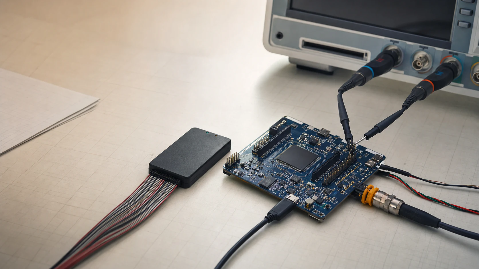
Measure from a defined source reference to a defined in-handler probe point. A GPIO transition occurs after architectural entry and includes preceding instructions and bus delay. Probe-high width measures only the instrumented code region.
Interactive race lab
Watch two valid increments produce the wrong result
Choose an implementation, then click the execution steps. The lane view separates the value in memory from each context's private register value.
Read, modify, and write are three separate actions.
Main contextReady to load counterlocal register: empty
Shared memorycounter = 5expected after two events: 7
ISR contextWaiting for interruptlocal register: empty
STEP 1 OF 6Main reads the current value
The value 5 is copied into a register. Shared memory has not changed.
What volatile actually providesObservable access: yesAtomic read-modify-write: noMutual exclusion: noEvent counting or ownership: no
Sharing contract
Choose the smallest primitive that preserves what the product needs
The correct primitive depends on information semantics, not habit. A Boolean can preserve readiness while still losing counts, order, and payload ownership.
COALESCED EVENT
Atomic flag with take-and-clear
Use when the consumer only needs to know that one or more events happened. Repeated arrivals intentionally merge.
A separate load then clear can erase a newly arriving event.
PROTECTION SCOPE
A data primitive and an interrupt mask solve different problems
A target-verified lock-free atomic RMW updates one atomic object without a software critical section. It can compile to multiple instructions and may retry after preemption. Atomicity of the flag does not establish payload ownership.
Added IRQ delay: no intentional mask interval in the verified implementationProtects: one atomic object and its defined orderingPreemption may force an implementation retryRTOS rule: priority still must satisfy the syscall ceiling
Evidence-driven debug lab
Start at the physical event and stop at the first broken fact
Select a symptom. The path marks what is proven, the waveform shows the distinguishing evidence, and the readout gives the next measurement instead of a guess.
01Physical event
02Raw status
03Local enable
04NVIC state
05Mask and priority
06Vector entry
07Source deasserts
Event exists, handler probe stays lowtime flows left to right
SYMPTOM | NEVER FIRES
Prove the request before blaming the vector
The first missing fact is often peripheral configuration, not the CPU. Read raw status and local-enable state before changing priorities.
First measurement
Probe the pin and inspect raw peripheral status.
Likely causes
Wrong edge selection, pin mux, clock, or local interrupt enable.
Corrective action
Repair the first broken fact, then continue down the path.
Proof of repair
Correlate the event reference, raw status, NVIC pending state, and ISR probe.
Heisenbug rule: if logging changes the symptom, treat that as timing evidence. Use a GPIO probe, cycle counter, trace, and counters before adding heavier instrumentation.
A worked mechanism
The deadline ends at the first freeing read
Expand the final UART drill without changing it: continuous 1 Mbit/s, 8N1, a 16-byte FIFO, threshold at eight bytes, and no reads during the interval shown. One complete character arrives every 10 µs.
01
Threshold reached
0 µs · 8 / 16
Eight bytes are stored and eight slots remain. This completed-byte boundary is t = 0.
↓Eight more character completions
02
Last free slot filled
80 µs · 16 / 16
Bytes 9–16 arrive at +10 through +80 µs. No capacity remains.
↓One more character completion
03
First byte cannot fit
90 µs · overflow
At +90 µs, the next complete byte needs a slot. The fixture has no extra receive capacity.
↓The handler has still not started
04
Handler body starts late
90.2 µs · missed
A 90.2 µs body-start latency is already too late. The first freeing FIFO read can only occur later.
Follow the stated ordering; spacing does not represent elapsed time.
Work it through
Compute the useful boundary
10 bits / 1,000,000 bits per second = 10 µs per byte. With eight free slots at t = 0, eight arrivals fit; the ninth at 90 µs needs a prior freeing read.
Measure threshold-to-first-FIFO-read and include the work before that read, not only exception entry or handler body start.
Watch for this
Do not count an undocumented receive shift register as extra FIFO capacity. A read simultaneous with arrival needs the target’s tie-breaking rule and margin.
Check your reasoning
Use the original drill’s threshold, read and overrun observations. This numerical fixture is from ASIC.FYI; the reference explains UART framing, not this fictional FIFO’s capacity or overflow behavior.
06 / 06 · System synthesis
Prove the complete interrupt design.
Connect every physical event to a timing contract, execution policy, software owner, overload response, and measured acceptance test.
Select a source. The summary identifies its product requirement and priority, while the detail panel explains why the mechanism, ISR, owner, overload policy, and proof belong together.
EventComparator trip
Hardware statePWM kill + latch
CPU policyConfigurable P0 report
Bounded ISRCapture evidence
OwnerRecovery state
ResponseRemain safe
ProofTrip, kill, handler probes
SOURCE 1 OF 5 | SAFETY CONTRACT
Hardware removes the hazard; software records it
The comparator-to-PWM path acts without CPU participation. The configurable priority 0 interrupt is a reporting path, not the safety mechanism.
Event semantics
A comparator sets a latched fault while an independent hardware path disables PWM.
Timing contract
PWM off within 200 ns. Measure trip-to-handler-probe separately.
Rate and burst
Rare and asynchronous. The response must survive a busy or masked CPU.
Mechanism and priority
Direct hardware shutdown plus configurable priority 0 reporting IRQ. No RTOS call.
Bounded ISR work
Capture cause and service time, or read a hardware-captured event timestamp. Service the documented latch, publish minimal state, return.
Remain latched safe, preserve first-fault evidence, and reject unauthorized restart. Count repeats only if hardware keeps exposing them without clearing the safe state.
How to prove it
Probe comparator, PWM disable, and a defined in-handler point. Verify trip-to-kill and trip-to-probe separately.
Integrated execution lab
Follow hardware, CPU, task, output, and proof on one timeline
Choose a system condition and then a phase. The trace highlights the active evidence so the story continues beyond exception return into ownership, product response, and verification.
Nominal acquisition and control releaseshighlighted column = selected phase
PHASE 1 OF 6 | EVENT
Independent hardware events become source state
DMA completion and timer compare set their own documented status. Neither source depends on the main loop noticing it.
Mechanism
Peripheral state preserves a request condition until service. A sticky bit can merge repeated occurrences.
State owner
DMA owns the filling buffer. The timer owns the compare status.
Acceptance check
Confirm the 6.4 ms block period and 1.0 ms timer period.
01 Claim
State the requirement and your design decision.
02 Mechanism
Explain the exact hardware and software path.
03 Tradeoff
Name latency, throughput, memory, and complexity costs.
04 Verification
Give probes, counters, limits, and worst-case conditions.