
Ethernet · IEEE 802.3
Ethernet Put the board on a wired network
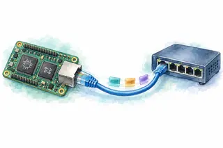
Use Ethernet when a board needs to communicate with computers or other devices across a wired network. Unlike SPI's selected peripheral or USB's host-scheduled transfers, switched Ethernet gives each device a separate link. Start with the MAC, PHY, and one frame before adding IP addresses, sockets, or TCP.
Ethernet wiring, timing and transaction
The board bus ends at the PHY
RMII is the digital connection between the MAC and PHY. The 100BASE-TX cable carries a different electrical signal.
TXD[1:0]
TX_EN→Bits + transmit enableRXD[1:0]
CRS_DV←Bits + carrier/data validMDC / MDIOPHY configuration + link statusMAC means Media Access Control: it handles frame fields and checks. The PHY, or physical-layer transceiver, turns the digital stream into cable signaling and recovers incoming data.
The clock source and PHY straps depend on the chosen parts. MDC/MDIO manages the PHY; it does not carry packet payload.
From a TX buffer to a received frame
Follow one frame through ownership, transmission, and a separate peer observation. Compare local errors with corruption seen only by the receiver.
- 1Free
- 2CPU
- 3DMA
- 4Free
REF_CLKTXD[1:0]TX_ENNo frame from this attempt yetNo per-frame Ethernet ACK. These are separate observations; their placement does not specify a timing order between devices.
Check the negotiated link. Read the PHY's resolved speed and duplex, then configure the MAC to match before queuing a frame.
Timing and model details
100 Mb/s, full duplex. The RMII inset shows one illustrative 0xA5 payload byte, least-significant dibit first. This is a stage model, not a cable waveform or a timing relationship between local completion and peer reception.
Forty payload bytes still need a full frame
An untagged Ethernet II frame includes addresses and error detection. Small payloads need padding to reach the minimum frame size.
14 + 40 + 6 + 4 = 64 bytesPreamble/SFD + frame: 72 bytes → 5.76 µs at 100 Mb/sIncluding the 96-bit interframe gap: 6.72 µs per repeated minimum-frame slotThe interframe gap is idle time, not another frame field. The MAC adds padding and FCS only when configured to do so; confirm what the driver expects in memory.
A network link or a host's peripheral?
Frames between network peers
Host schedules transactions
Choose Ethernet for network access, such as an instrument serving several computers through a switch. Add the required IP and transport stack for those services.
Choose USB for a host-attached device, such as a local measurement accessory. The USB class and endpoints describe how the host communicates with it.
A connector alone does not supply either software model. Both need drivers, buffering, and a defined application protocol.
Compare USB’s host-scheduled transfer →Follow a transaction
Advance here or in the transfer above. The highlighted operation and wire state stay on the same step.
if not link_up(): return LINK_DOWN
desc = try_reserve_tx()
if desc == NONE: return BUSY
fill_frame(desc, payload)
publish_to_dma(desc)
status = bounded_tx_wait()
reclaim_released(desc)
return status // local result only- Who drives
- Each PHY controls its own transmit pair; no frame queued yet
- Sent so far
- No frame submitted
- Response so far
- Local PHY reports 100 Mb/s, full duplex
Link ready · no frame queued
Why this step mattersStep 1 of 7, Check the negotiated link. Read the PHY's resolved speed and duplex, then configure the MAC to match before queuing a frame.
Implementation notes
Conceptual driver operations, not register-level code. publish_to_dma includes the target's cache maintenance, memory barriers, descriptor ownership change, and doorbell. bounded_tx_wait uses a configured deadline; on timeout, recovery must stop DMA access before any buffer is reclaimed. reclaim_released returns only a descriptor and buffer that DMA no longer owns. The success and bad-FCS fixtures both complete locally without a TX error. Peer reception is a separate observation for teaching, never a value returned by this TX API. The displayed stages do not define the relative timing of the two devices.
Common mistakes
Confusing Ethernet with TCP/IP
A MAC address belongs to link-layer delivery. IP addresses, routing, and transport reliability are separate mechanisms above this frame.
Reading TX complete as delivered
Local completion permits buffer reuse. It does not prove peer reception or application processing.
Changing a DMA-owned buffer
Publish visible data, transfer ownership, and wait for release. A timeout alone is not permission to reuse memory.
Treating RMII as cable wiring
RMII joins MAC and PHY on the board. The PHY and magnetics provide the differential cable interface.
Check negotiated link mode first, then descriptor ownership, local TX status, and peer receive counters or a capture. A valid link LED does not prove frame delivery. To test corruption, inspect the receiver's FCS-error counter; ordinary packet captures may omit frames rejected by the NIC.
Further details and primary sources
- MAC and PHY have different jobs
- The Media Access Control block assembles and checks frames. The Physical Layer transceiver encodes the cable signals and reports link state. RMII joins these blocks on the board; it is not the cable protocol.
- A switch joins separate links
- Each full-duplex link has independent transmit and receive paths. Switches learn source MAC locations and forward frames toward destination ports; unknown unicast and broadcast traffic may be flooded. This lab observes only one link, not a complete switched delivery path.
- Completion has a local meaning
- The driver publishes a buffer to DMA and waits for ownership to return. TX completion allows reuse under the controller's rules. It is not a peer ACK. A receiver rejects a bad FCS in this fixture; higher-layer protocols decide whether and when to retry.
Example scope
One 100BASE-TX full-duplex link with RMII, an untagged Ethernet II frame, hardware padding/FCS, a preconfigured destination, and no cache-coherency fault. Peer destination filtering passes and receive capacity is available. Bad FCS is injected on the link after local transmission. VLANs, gigabit PHYs, half-duplex collisions, TCP/IP setup, real DMA register layouts, and waveform-level cable encoding are outside this model.
Primary sources
- Microchip PIC32 family manual · Ethernet frame fields
- TI AN-1405 · RMII signals, clocking, and timing
- Microchip GMAC · TX descriptors and buffer ownership
- Microchip Ethernet MAC · padding, FCS, and interframe gap
- Microchip MAC receiver · FCS validation and error handling
- Cisco · MAC learning, forwarding, and flooding
Updated