
Q030FreeSystemVerilog
Generate and synchronize a Gray-code counter
Interview prompt
Question
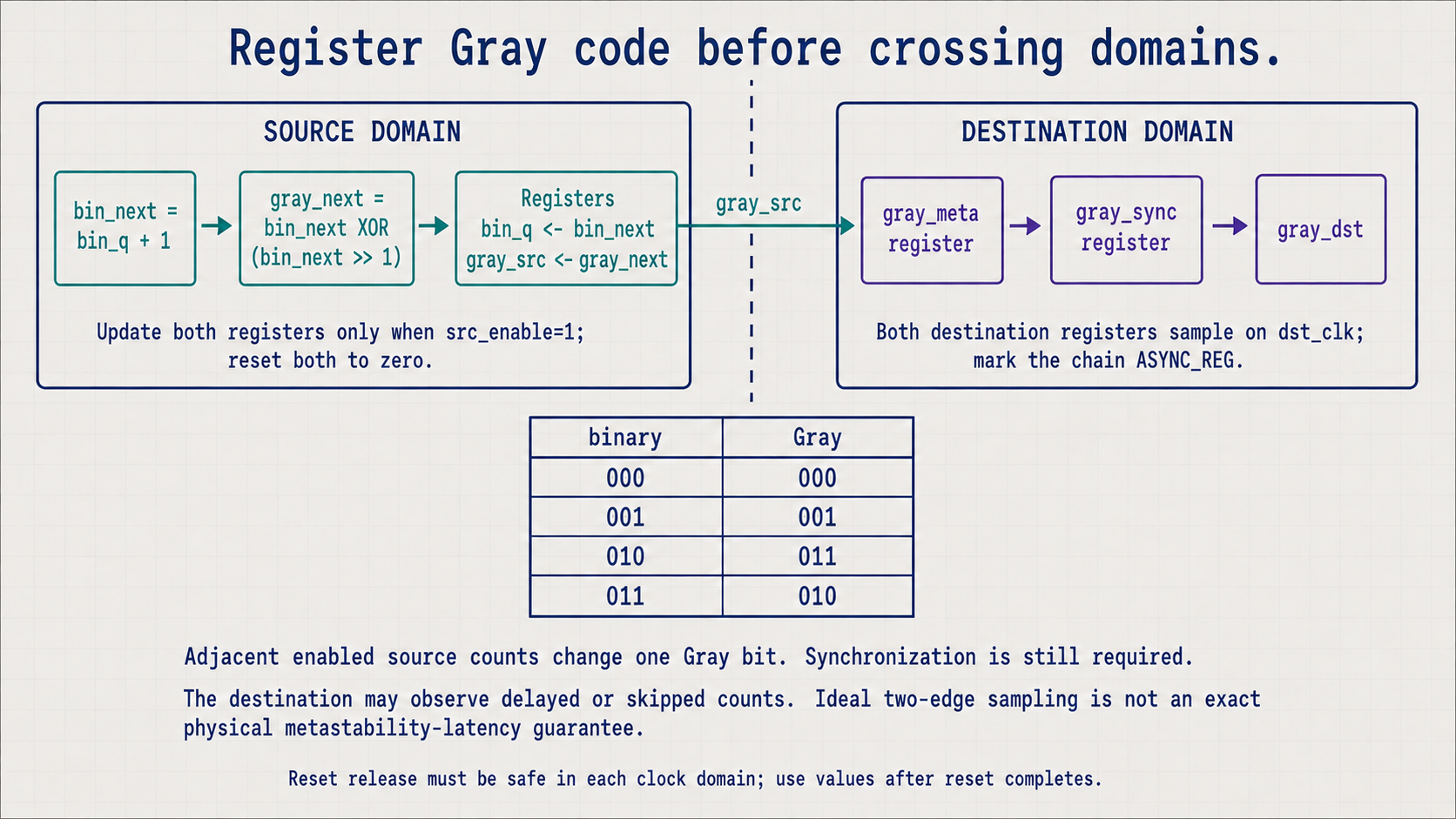
Design a counter with positive static width W whose registered Gray code changes by one bit per enabled source increment, then synchronize that Gray value into a destination clock domain. The consumer must tolerate delayed or skipped counter values. Assume each reset deasserts safely in its own clock domain and counter values are used only after the domains have completed reset.
Candidate starting point
Implementation scaffold
module gray_counter_cdc #(
  parameter int unsigned W = 4
) (
  input  logic         src_clk,
  input  logic         src_rst_n,
  input  logic         src_enable,
  input  logic         dst_clk,
  input  logic         dst_rst_n,
  output logic [W-1:0] gray_dst
);
  logic [W-1:0] bin_q, bin_next, gray_src;
  (* ASYNC_REG = "TRUE" *) logic [W-1:0] gray_meta, gray_sync;

  always_comb begin : next_binary_count
    // TODO: Implement next_binary_count using the supplied state and interface.
  end

  always_ff @(posedge src_clk or negedge src_rst_n) begin : source_count_and_gray
    // TODO: Implement source_count_and_gray using the supplied state and interface.
  end

  always_ff @(posedge dst_clk or negedge dst_rst_n) begin : destination_sync
    // TODO: Implement destination_sync using the supplied state and interface.
  end

  assign gray_dst = gray_sync;

  property p_one_gray_transition;
    // TODO: Implement one_gray_transition with the stated clock, reset and timing contract.
  endproperty
  a_one_gray_transition: assert property (p_one_gray_transition);
endmodule

// TODO: Explain registered Gray transitions, skipped destination observations, metastability reduction and physical crossing constraints.
Reviewed example
Trace one case
Input
W=3. Starting from binary 0 / Gray 000, enable source increments to binary 1, 2, and 3. For each illustrated increment, hold the source value unchanged across at least two subsequent destination sampling edges.Expected output
Source Gray codes are 000, 001, 011, and 010. In ideal RTL sampling, each held code reaches gray_dst after the second destination edge that follows its source update.Only one source Gray bit changes per increment. This example holds each code long enough to observe it; a faster source can produce intermediate values that the destination never sees. Synchronizer flops reduce metastability propagation risk but do not give an exact physical two-edge latency guarantee.
What to cover
Requirements
- Increment the binary source count by at most one on each enabled source edge.
- Register Gray code derived from the next binary value.
- Use a two-flop destination synchronizer for every Gray bit and mark the chain for CDC tools.
- Explain that Gray coding limits transition ambiguity but does not remove metastability or replace synchronization.